Examples of some Custom Projects
Here is an excerpt of some customer projects from the past 15 years.
Since most of the solutions were created very customer-oriented, they are only available on request.
If you are interested in individual projects, please send me a message and I will put together an individual package for you with the desired functions.
Individual functions are summarized in etaCAD:Tools and available as separeate App.
The settings of the respective functions are stored in an ini-file. This can be stored and managed for multiple users at a central location.
 Automatic Part Extents
With certain Inventor on-board tools, you can determine the dimensions of all elements. This goes from individual lines to surfaces, bodies, components and even entire assemblies. These dimensions are based on a RangeBox that encloses the elements and whose side surfaces are always parallel to the main planes. If the component is now skewed in space, this method delivers wrong values. Moreover, the direction of length, width and thickness is not defined.
The etaCAD dimension element provides a remedy. It expects the input of a plane surface as well as a straight edge. These inputs define a coordinate system on the component, which is used to determine the true dimensions, independent of the orientation of the component in space. The input can be done both in the part and in the assembly environment. When saving, the dimensions are automatically updated and written to the iProperties.
Inventor Standard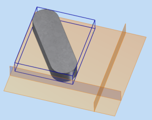 |
etaCAD |
Optionally, the textures on the top and bottom sides can be automatically aligned along the longitudinal direction.
If parts are provided with a dimension element, the longitudinal direction can also be retrieved automatically for these parts in the drawing view. The user has the possibility to define his own symbol.
Bauteil |
Zeichnungsansicht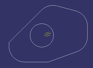 |
A table creates an overview of all components in a group with the associated dimensions and coatings:

You can find more detailed information on page Abmessungen.
 DrawingList
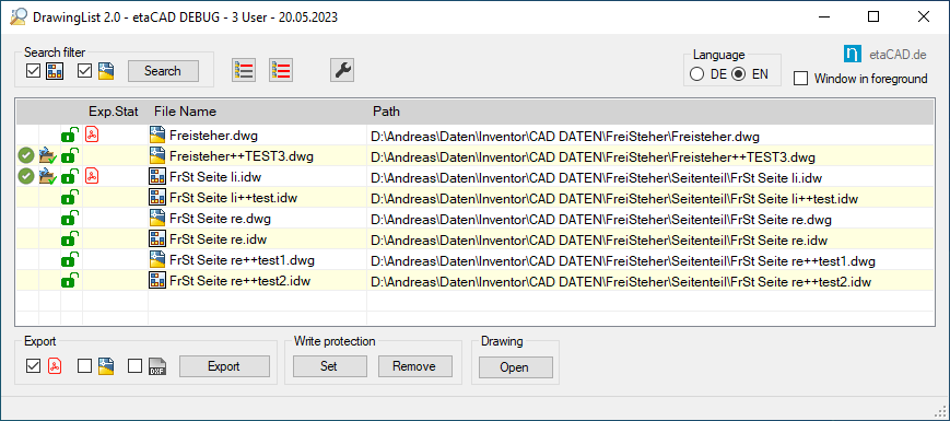
The window lists all drawings of the current assembly including their children and offers the possibility to export them as PDF, DXF and AutoCad DWG. There are various options to specify the file name and location and to add a print stamp. Alternatively, drawings can be added to the list by drag & drop. The fields inform about the export status and about the file write protection, which can be set and removed as desired.
This window is availlable with English user interface.
You can find more detailed information on page DrawingList.
 Parameter-Dialog
The parameter dialog offers the possibility to edit the named parameters of the selected objects. The groups with their associated parameters are defined in the settings file. Numbers with units and/or parameter names are permitted as inputs, which are also checked for plausibility. In case of errors in the expression, writing is prevented. Different symbols give information about the use and correspondence in the selected objects. A check of the units prevents writing of the parameters in case of conflicts.

 iProperties-Dialog
Analog to the parameter window you can edit the iProperties of one or more selected elements at the same time. The iProperties can be defined in groups in an ini-file. There you can also specify default values for the different iProperties.

 SuperCopy
With this function you can duplicate assembly components including their constraints in the assembly. This makes sense, for example, if the corresponding component is to appear several times in the assembly, but these are arranged irregularly and therefore the pattern command is not possible. This leaves only the option of inserting the corresponding component several times and positioning it with relations in each case.
Especially with irregular row arrangements often only one constraint varies. The others always refer to the same partners, but must always be completely recreated using Inventor on-board tools. SuperCopy simply takes these relationships and offers the possibility to vary single or multiple values.
In addition, components that are connected to the component to be copied, including their relationships, can also be copied.

 Copy
Copy
A function for copying individual components or the complete assembly structure including drawings. A wide range of options is available and an extremely flexible option for automatically designing the new file name. A status column informs about possible conflicts and the copying progress.

 First Views
The command is used to create additional first views in drawings. The part is selected directly by selecting an edge in an existing drawing view. Then the usual dialog window ‚First view‘ opens to make further settings of the view and to create additional parallel views. This saves the user from having to constantly switch between the model and drawing environments.
![]() Another button then labels all views on the sheet with the corresponding item number from the parts list and the corresponding quantity.
Another button then labels all views on the sheet with the corresponding item number from the parts list and the corresponding quantity.
 Clone
Clone
The command opens a toolbar with which iProperties and material can be transferred directly in the assembly from one part (source) to other parts.

 Material
A dockable window shows the material of the selected part of an assembly in the status line. Likewise, a new material can be assigned to this component(s). The materials are sorted according to their library and category.


 Write Protection
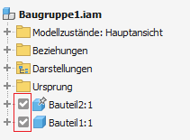
The two buttons can be used to activate and deactivate Windows write protection for any selected files (parts, assemblies and drawings) directly in Inventor. Write-protected files are then protected against unintentional modification. This provides much more security against accidental changes of data, especially if you work without data management as it is often the case in smaller companies.
Write-protected files are marked in the browser by an additional icon ![]() .
.
 QuantityProp
The window offers the possibility to write in all parts of an assembly the total quantity of the respective part into a separate iProperty. In addition, individual iProperties can be assigned a value and check whether certain iProperties are present in the files or a value is assigned. All iProperties are defined in a settings file and any default values are entered there.

 Sheet-Templates
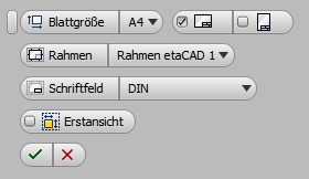
The button opens a toolbar for inserting a new sheet into the drawing. You can make various settings for the new sheet in advance. Sheet sizes from A4 to A0 are available.
The listed frames and title blocks are available in a separate drawing and are then inserted into the current drawing depending on the selection.
If you work for several clients with different drawing templates, you can reduce the administration effort with this tool. You have an empty template with a few basic settings and a second template that contains all the frames and title blocks. When creating a new drawing, you get only the drawing resources on the sheet that you need. This way the drawing is not overloaded with numerous unused frames and title blocks. The advantage is that you only have to manage two templates, and not a separate one for each client.
In the part and assembly environment, you can use the command to directly create a new drawing based on the currently opened or a selected component.
 Hide Phantoms
The function runs through all view representations of the assembly and hides all parts with the BOM property ‚Phantom‘ of the current assembly and its children. Additional filters can be specified in the settings file to limit the selection to certain materials. If no material is specified, all phantom parts are hidden, regardless of the material
 BOM Export to Excel
In this category, several projects were realized that export customer-specific data from the parts list to Excel. The data is structured, sorted, summarized and displayed in various ways.
Likewise, it is possible to load additional information from inventory files and also output it on the Excel parts list.
 PDF Drawing Export
The PDF export offers the possibility to export the current drawing, the current drawing sheet or all opened drawings as PDF.
By appropriate values in the settings file, the user can influence various properties of the output. In addition, it is possible to assign a specific value to a user-defined iProperty before the export. This can then be queried on the drawing as a print stamp (text field) and thus contain, for example, the current user and the date of PDF creation.
 Align Components
The command aligns all selected components by creating three alignment relationships to the origin of the assembly. Optionally, the user can specify an offset, or individual directions can be left free. In another mode of operation, another component can also serve as a fixed reference for alignment. This is selected separately during the command and marked in a different color. During the command, it is possible to switch between both modes as desired, as well as to add and deselect further components as desired.
The status bar at the bottom of the screen informs about the required input while the toolbar is visible.
Mode 1: Align to the origin of the assemblyMode 2: Align to the origin of another component
 Update Drawing Ressources
Auf Knopfdruck werden die Schriftköpfe und Rahmen entfernt und durch die der neuen Vorgabe ersetzt und auf die Blätter übertragen. Gleichzeitig werden die Stile aktualisiert und die Benutzersymbole ergänzt. Sämtliche Eingaben bleiben erhalten und in die Felder der neuen Schriftköpfe und Rahmen übertragen.
At the push of a button, the title blocks and frames are removed and replaced with those of the new template and transferred to the sheets. At the same time, the styles are updated and the user symbols are added. All entries are retained and transferred to the fields of the new title blocks and frames.
 Open All
The command opens all selected components of an assembly. It is also available in the context menu as soon as several valid components are selected.
 Copy Constraints
The function copies the selected assembly constraint. This is quite useful for creating positional views.
 Painter
Colorize parts or assemblies across the entire assembly structure. Certain characteristics such as the BOM structure (Normal, Purchased, Reference) and certain iProperties determine the representation.
Before
After

 Save and Replace incl. Drawing and Substitute
The selected element in an assembly is replaced by a copy. At the same time, the associated drawing is searched and copied. In addition, the associated LOD objects can be copied and referenced to the new file, just like the drawing.

 Derive new Source
Assign a new source for derived components.
 Profile-Editor for former iParts
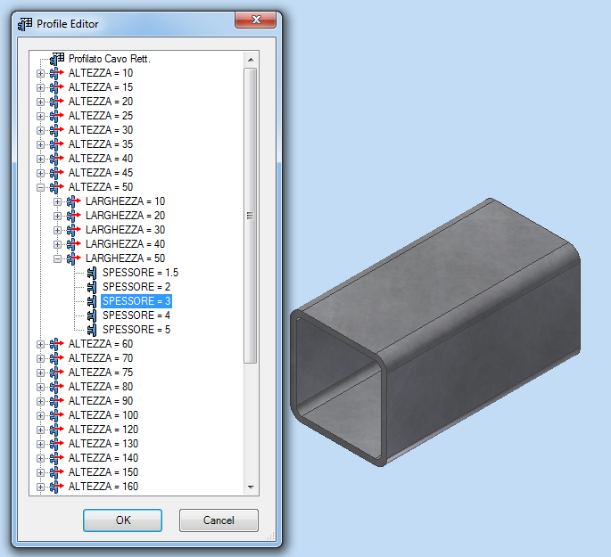
If the table is deleted in iParts, they are transformed into normal parts and the functionality of the iPart is lost. The profile editor recognizes by certain features that it is a former iPart and brings the functionality back temporarily to change certain parameters and iProperties.


 Copy Informationen to Clipboard
The modified context menu offers the option to copy certain iProperties or the file path to the clipboard.
Furthermore, an additional button in the context menu allows you to display the selected components directly in Windows Explorer.

 Open Drawing
The default command in the context menu is overridden to open drawings where the drawing file name is different from the part name or is not in the same path.

Part Number Check before Saving
When saving, the part number in the iProperties is compared with the file name and a warning is shown if they do not match.

 Reset Browsername
Before saving, all browser names are reset to their default value in the background. Confusion due to renamed names is not possible any more.
Rename Browsername
In opposite to the upper point, there is also an automatic function which renames the browser names after any iProperties and additional text and always keeps them up to date.
 Rename Sketch for Section Views
The function searches for all section views in the drawing and automatically renames the associated sketch in the browser so that it corresponds to the name of the section view. This makes it possible to assign the sketch to the associated view in the browser at first glance.
